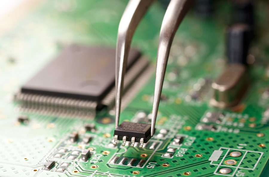
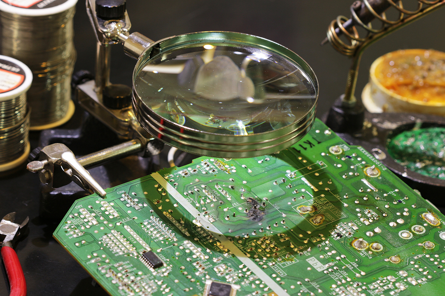
Printed circuit boards (PCBs) are central to nearly every single electronic piece of equipment and machinery manufacturers use in factories today. A PCB’s chief job is to connect electrical components, relaying input signals to appropriate control actions. Because they’re so central to electromechanical operation, PCB failures can be debilitating and need resolution quickly.
Not every PCB failure is the same. Different problems affect boards in different ways — from short circuits to spotty operation, complete failure, and more. Here are some of the most common catalysts for PCB malfunction and failure:
- Burning or burnt components
- Debris or environmental damage
- Age-related power issues
- Soldering problems
- Chemical fluid leakage
Not only does each of these problems stem from a unique catalyst but each also causes unique interruptions maintenance and repair technicians need to properly diagnose during PCB inspections and repairs. To make sure they are addressing the right components, comprehensive troubleshooting is paramount.
Troubleshooting approaches
PCB troubleshooting is a delicate process not only because the boards themselves are small in scale but because each of the individual components that comprises it is also sensitive. Repair techs must approach PCB maintenance with a keen eye for detail and mind for careful handling.
To uncover the reason or reasons behind a PCB failure, it’s important to be methodical in troubleshooting and inspecting. Here are the four crucial steps to take — ranging from broad inspection to detailed troubleshooting — to get to the bottom of a PCB malfunction:
- Visual inspections — You can see a lot through a visual inspection. Burned or eroded components are the easiest to spot, which signal overheating issues or chemical fluid leakage as reasons for malfunction. You can also identify missing components, indicating a flawed or defective board. Finally, clean away debris before probing the board deeper for issues.
- Physical inspections — With the board under load, a physical inspection may yield additional insights. Hot spots are easy to feel, which can signal potential burnt components that may not be visually identifiable. Probing with an oscilloscope can also help detect impedance issues resulting from age-related power problems.
- Component testing — Delving deeper into the PCB’s many components, you can test the integrity of batteries, capacitors, resistors, inductors, diodes, switches, and transistors. Use a multimeter to compare values to factory standards to spot discrepancies. Often, it’s these individual components that fail and eventually lead to larger failures of the entire PCB.
- Integrated circuit testing — A final stage of PCB troubleshooting involves testing integrated circuits (ICs). An oscilloscope also comes in handy here. Unfortunately, it can be difficult to test ICs, depending on how many are present on a PCB or the nature of the circuit itself. The best approach is to identify a known good circuit and test all ICs against it to recognize problematic ones.
Following these four steps helps ensure techs give complete and thorough attention to each circuit board during troubleshooting. The methodical nature of this approach also allows repair techs to assess all the common causes of PCB failure so they don’t overlook issues.

What to do with a failed PCB
What happens if your PCB suffers a catastrophic failure? According to the United States Environmental Protection Agency (EPA), there is an amalgam of hazardous parts within PCBs that necessitate proper disposal. Turn over PCBs to a recognized recycling authority so professionals can properly strip them of their materials and salvage their parts.
Like any part of industrial machinery that’s worked tirelessly each day, PCBs need a little attention and some minor repairs to stay functional. Heading off issues with a thorough inspection means preventing the type of catastrophic failure that might warrant recycling!
